
These instructions and the pictures relate to our standard 15″ PoS units. In technical paperwork this model is referred to as a Ter-Fly 335. This article deals with setting up the physical kit, in particular removal of plastic panels and routing of the various cables. If the machine has come to you direct from the manufacturer (Box Technologies), it will not have the till software installed ready to use. See “Next Steps” at the end of this article. If the machine has come from Tengo with software installed, refer to the article “Configuring a new till machine with software installed”.
1. Unpacking the box
Carefully remove the till unit from the packaging.

Note there may be cables included in the packaging that you will not use, e.g in the bag bottom right of Fig1. The PoS Driver DVD will not be needed either, but can be retained if you wish. You will need the 2 part power cable.
The main unit has removable panels so that cables such as the Power lead, Printers, Bar code Scanner and Keyboard USB cables can be routed tidily within the stand. We will look at how to remove these panels and route the cables. Keep the screen protector on at this stage.
2. Removing the stand panel
Hold the panel firmly at the bottom where the cut out is, hold the stand with your other hand and pull the panel away from the stand. It requires some force to remove it.

3. Removing the socket cover panel
Next remove the panel behind the bottom of the screen, which gives better access to the various Ports and sockets. It may be helpful to rotate the screen back on its stand, then place the unit screen down on a flat surface to allow better access to the panel.

You may need a flat blade screwdriver or similar to help prize the panel off. You should hear a click as one side is released, pull that side toward you slightly so it does not re fix while you work on the other side. Release one side at a time as below, then the panel will pull away toward you.


Note the clips on the edges (front of picture) and flanges on the left of the picture, which is why the panel should be pulled toward you once the clips have been released. These fit back into slots on the main unit when you refit the panel.

4. Identifying the ports and sockets to use.
Close up of Ports and sockets –
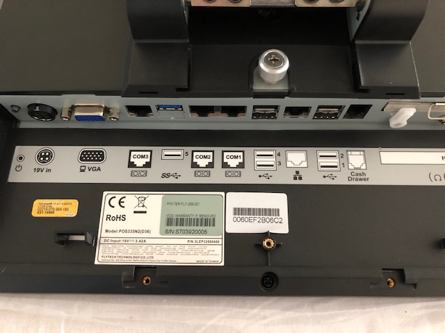
Fig 7.
From the left, there are 10 sockets, from 1 – “19v in”, to 10 – “Cash Drawer”. You will only use the following, numbered from left to right –
- 1. This is where the power lead goes. Flat side of the plug toward the unit.
- 4. This is a fast USB port. You could put the receipt printer USB lead here
- 7. 2 standard USB ports
- 8. Ethernet connection for your wired broadband connection
- 9. 2 more standard USB ports
The standard USB ports are typically used for a Keyboard, Bar Code scanner, Label printer and maybe a customer facing display (this is an optional extra). Once the Label Printer has been connected, try to keep that always in the same socket, should you ever have to unplug it. Printers like to be connected to the same port used when they were set up, whereas the other items are “plug and play” and it doesn’t matter which port you use.
Numbers 2,3,5,6 and 10 are not used in a typical set up. The cash drawer is plugged in to the back of the receipt printer, not socket number 10 marked Cash Drawer.
5. Routing the cables
The panels removed are easier to put back than they are to remove! Stand the unit in its proper position on the stand. Using the monitors power lead as an example, take the 4 pin plug end and from the back of the unit thread it through the aperture and plug it in to the “19v in” socket. Do this with all the USB cables / Ethernet cable, plugging them into the appropriate socket.

Once all cables are threaded through, replace the cover panels

You will probably need to tilt the screen back on its stand to replace the panel that covers the sockets. There will be room for all the cables, they will need to be arranged so that there are no sharp bends, and the plugs remain squarely in their sockets. The machine will work of course even if this panel is not replaced. Depending on the situation of your till, you may feel happy leaving it off, or prefer it on for neater appearance and to deter anyone from tampering with the cables.
The stand cover replacement is straightforward.
Example of a unit with multiple cables, Fig 10 – this one also has a Customer Facing 2 line display. It is sat on the cash drawer in this case.

6. Fitting a Customer Facing display
If you have requested a CFD, it may come attached to the unit already. if it does not, fitting is easy. The CFD will be in a separate box. This is one, face down showing the fixing plate and USB lead.

We have to remove the stand from the screen on the main unit. Rotate the screen back on the stand, then place the unit screen down to reveal the fixing screw, the larger silver one in the center of the image below.

Losen the screw – it can be done by hand or with a screwdriver. It will spring up a little when it is lose. carefully remove it, then the stand fixing plate will pull slightly forward toward you, releasing it from 4 fixings. Lift it gently to one side, being careful if there are any cables running through it, We have the power cable in the images here. This is the underside of the stand –

The screw in the middle of the image above now needs to be removed. It has a semi-circular metal loop to help do this by hand. Remove this and you can then prize of a small plastic panel. The base plate of the CFD fits in the same place instead.

The CFD is now secured in place by replacing the screw with the metal band through the hole it originally came from, just above the USB cable as seen above.
Then re-attach the stand, now with the CFD attached, to the monitor by placing it on the monitor and sliding it up a little so the 4 pins engage with the 4 notches on the stand plate . Secure with the larger round screw removed earlier. Replace the cover to conceal the wiring.


7. Power Switch
On the Box 335, the power switch is on the edge of the screen, bottom right corner. It is recessed so that it can not be turned off accidentally.


8. Next Steps
Machines such as the one shown here that are received direct from the manufacturer do not have the TengoPoS software installed, ready to use. When you have the machine set up, powered and connected to the Internet, double click on the Icon that says Run Me First! (3rd down on the left, in the image below) to Install Splashtop. This enables us to gain remote access to the till to complete set up.

Answer Yes to the “Do you want this app to make changes”, and when Splashtop Streamer has installed, answer Confirm in the Tengo Support box. Splashtop Streamer will now be open on screen, the tabs on the left read Status, Settings, Security etc down the page. Make a note of the Computer Name on the top line under Status, so you can quote this temporary name later (TENGOXXXX). Click on Security and Blob the “No additional password” line. Close the program using the X top right.
Contact Tengo Support to arrange for an engineer to call and complete set up remotely. You can do this by contacting us from the support website – double click the Tengo Support icon on the desktop, bottom one. Select Submit a support ticket from the top menu, and complete the details including the machine name you noted earlier. In the “Your Issue” box explain the new machine is powered up, splashtop installed and ready for the remote installation of software. Please note this can take a couple of hours or more, to install the various items of software and allow for your new machine to synchronise to your organisations database. Tengo may not be able to do this immediately, but will respond promptly to your support ticket to arrange a time with you.